Honeywell Spyder Wiring Diagram
The honeywell home trademark is used under license from honeywell international inc. The nine controllers are bacnet ms/tp network devices designed to control hvac equipment.

Honeywell Th9421c1004 Wiring Diagram Free Wiring Diagram
Honeywell thm4000r wiring diagram pdf (honeywell_thm4000r_6709.pdf) download.

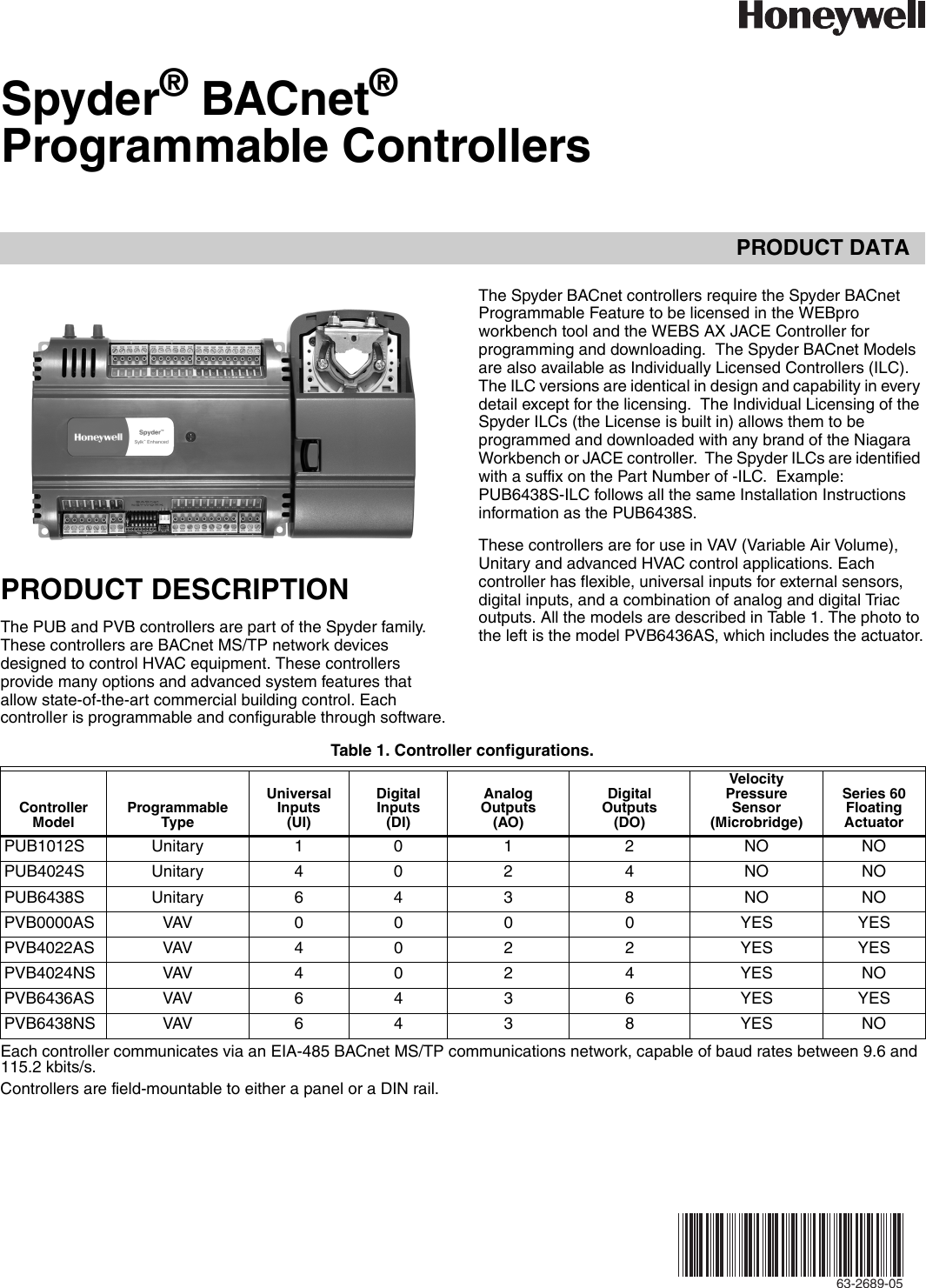
Honeywell spyder wiring diagram. Spyder® bacnet® programmable controllers application the pub and pvb controllers are part of the spyder family. Up to 15% cash back building management solutions tailored for you. Honeywell spyder 6 about honeywell spyder this document serves as a guide to configure and use the honeywell spyder tool.
Your local honeywell environmental and combustion controls sales office (check white pages of your phone directory). I can't believe i spent nearlt $ on my alarm now that. Contains all the essential wiring diagrams across our range of heating controls.
The exported wiring diagram pdf can then be used to import into cad programs like visio and autocad for use in submittal, saving you time. The diagram below represents the internal schematic of the digital output circuitry. I would like to see the wiring diagram for a mr2 spyder.
Honeywell tra averaging wall mount thermostat sensor 10k ohm direct wired wall modules used with honeywell excel controllers, w, w controllers, and spyder unitary controllers. Ip20 provides, ingress protection against solid objects over 12.5mm e.g. • programming is built directly into the spyder tool.
It provides the following features: Honeywell spyder controllers give you affordable, flexible control for today’s systems, but they’re also designed for control as systems evolve. • field configurable and programmable for control, input, and output functions using the niagara framework® software.
Disconnect power supply before beginning wiring or making wiring connections to prevent electrical shock or equipment damage. Wb10707 spyder micro wiring box smart for now. Traded in after 24,000 miles.
Up to 15% cash back spyder model 5 compact vav with integrated actuator 24 vac 4 2 9 3 1 yes 72 hours data retention table 2. Honeywell thm4000r wiring diagram pdf. Your local honeywell environmental and combustion controls sales office (check white pages of your phone directory).
Our wiring diagrams section details a selection of key wiring diagrams focused around typical sundial s and y plans. Our product range is designed to provide the homeowner with the best in comfort, energy and health solutions. • installation can be done locally or remotely.
The existing spyder wire sheet. Terminals for relay neutral wiring x 14, 15 in1, ro1 input for relay 1, output of relay 1 type 1 Using our comprehensive range of controllers, field devices and software, we’ll help you customize a system to fit your building and your future.
Models are available with user selectable setpoint adjustment dials in. Controller wiring diagram (model pub6438s. Spyder with relays os numbers wiring the digital outputs of the spyder with relay are designed.
Follow honeywell cabling and grounding recommendations. Spyder controllers use a zio wall module or honeywell rapidbalance™ for variable air volume box (vav) balancing. If possible, install the basrouter at one end of the ms/tp segment.
Walls, as well as in wiring cabinets or fuse boxes. By leveraging the technology used in the spyder controller, the stryker controller meets any application currently met by the popular xl10 and then some. If someone could help me out with a 'up toyota mr2 spyder wiring diagram, i'd greatly appreciate it!
Honeywell tr70, tr71, tr75, zio®/zio plus lcd wall modules manual. Note, you can use a conventional thermostat for a heat pump system, however, em heat can only be controlled. Replacement parts device model description power supply uis aos total no.
1985 douglas drive north golden valley, mn 55422. It provides a graphical environment to program honeywell spyder controllers. With everything from plenty of inputs and outputs to
About honeywell home we are the leading suppliers of domestic heating and combustion controls in the uk with products that include time, temperature, gas and water controls. A typical wiring diagram is shown. The spyder lon controllers require the spyder programmable.
Optional accessories must be linked to each eim separately.

Honeywell Universal Remote Pub1012S Users Manual 63 2689—05 Spyder® Programmable Controllers

Honeywell Co2 Sensor Wiring Diagram

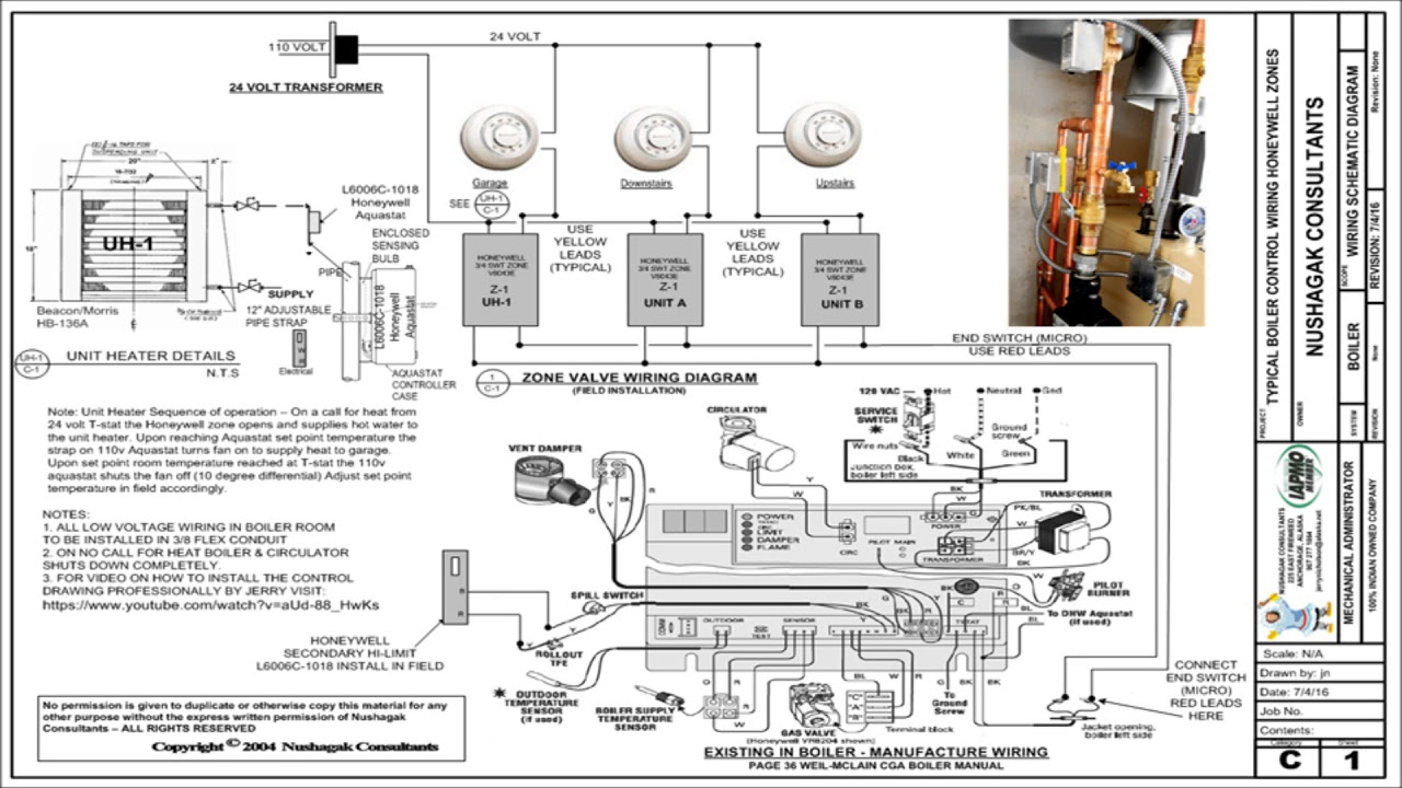
HONEYWELL ZONE CONTROL WIRING DIAGRAM Auto Electrical Wiring Diagram

HONEYWELL ZONE CONTROL WIRING DIAGRAM Auto Electrical Wiring Diagram
Article Using the BASrouter with a Honeywell Spyder Controller

Honeywell Honeywell Universal Remote PVB4022AS User's Manual Page 14 Free PDF Download (24

Honeywell TR21, TR22, TR23, TR24 Wiring and DIP switch settings

Honeywell Universal Remote Pub1012S Users Manual 63 2689—05 Spyder® Programmable Controllers

Honeywell Universal Remote Pub1012S Users Manual 63 2689—05 Spyder® Programmable Controllers
Floating SPDT Actuator with 35 lbin., nonspring return, 24 Vac ±20 ML6161B2024/U

Honeywell Zone Valve Wiring Diagram Cadician's Blog

Honeywell Th8320r1003 Wiring Diagram Free Wiring Diagram

Honeywell Universal Remote Pub1012S Users Manual 63 2689—05 Spyder® Programmable Controllers

Honeywell Universal Remote Pub1012S Users Manual 63 2689—05 Spyder® Programmable Controllers

Why Honeywell Sylk is a Must Have
honeywell alarm system wiring diagram Autoguard Alarms

WLKFWM Wireless Receiver User Manual 620291_D.fm Honeywell

HONEYWELL ZONE CONTROL WIRING DIAGRAM Auto Electrical Wiring Diagram
